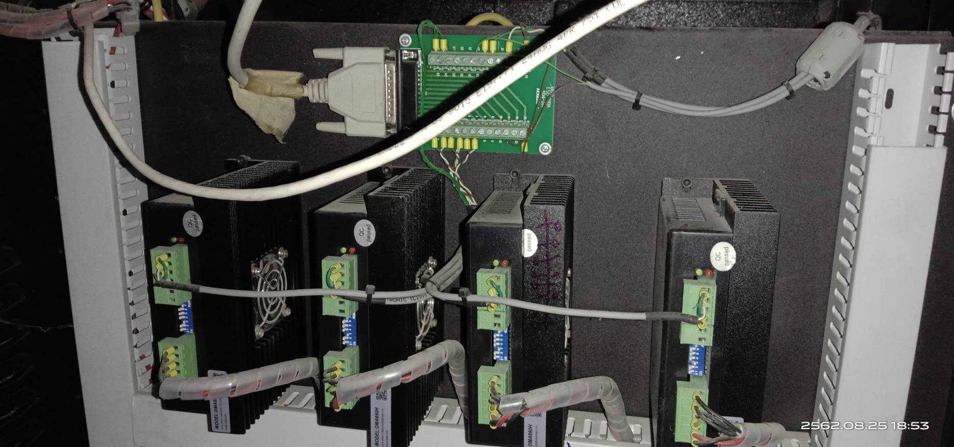
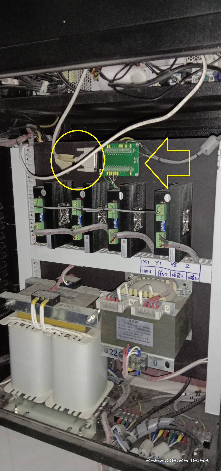
Mach3 USB 4 Axis 100KHz.
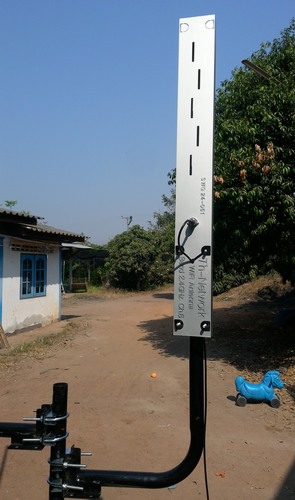
เลขกำกับบอร์ด BSMCEO4U-PP
ต่อเนื่องจากกระทู้นี้
www.thaihotspotnetwork.com/index.php/topic,600https://buildyourcnc.com/Item/electronicsAndMotors-electronic-component-breakout-Mach3-USB-BoardIntroduction:This USB Controller will run Mach3 through a standard USB port on a PC. Sold and shipped next day or quicker from the United States. Warranty and support available.
Description:If you're tired of needing a parallel port and an outdated PC to run Mach3, this is the solution you've been waiting for! Our newest interface board runs through any standard USB port for communication. You simply need to install the card's plugin for Mach3 and follow the setup instructions.
Note: We are an authorized Mach3 distributor. Please purchase an official Mach3 license to run Mach3. If you use a counterfeit license, you will not be able to receive support for this product.
Package Includes: Mach3 USB Board and USB Cable
Manual and Driver Downloads Click On Links to Download or View
 USB Motion Driver Link 1 USB Motion Driver Link 2 Mach3 Configuration File
 RIGHT CLICK AND SELECT "SAVE AS"
Setup InstructionsStep 1: Installing Mach3: You will need to purchase a Mach3 license and download the software. If you already have a licensed copy of Mach3, skip this step.
Step 2: Download the USB Motion Driver RnRMotion.dll from the link above and copy and paste the file into your Mach3 Plugins folder Example: "C:/Users/ProgramFiles/Mach3/Plugins"
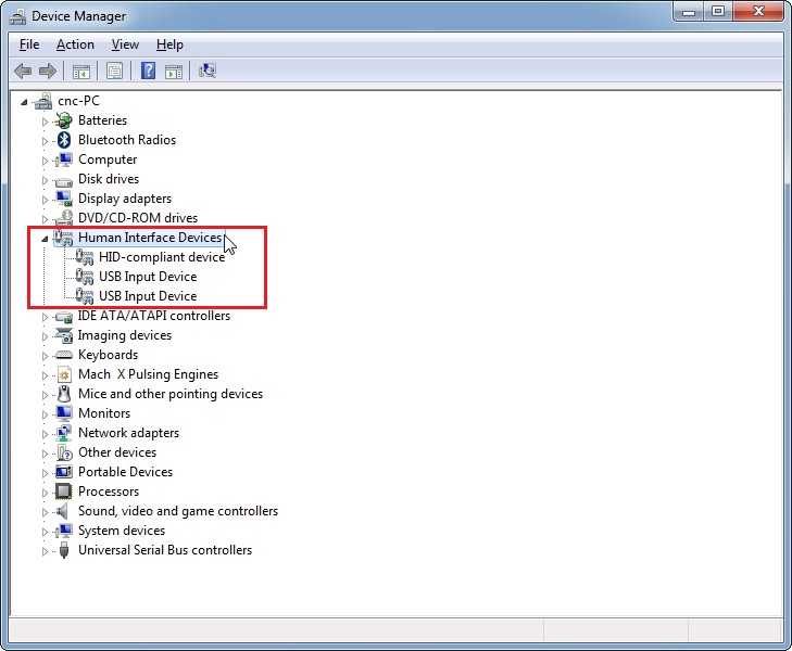
Step 3: Make sure you board is connected to the PC via USB cable. It should automatically recognize the USB device.
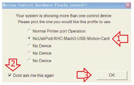
Step 4: Open Mach3 and you should be prompted to select a driver. Select the "RnRMotionController" and check "Don't ask me again". This will allow your board to communicate with Mach3.
Step 5: Download the XML Mach3 Config File above by right clicking on the link and selecting "save as". Save the Mach3Mill.xml file in your Mach3 root folder.
Note: An additional power source is required for the limit switches and spindle portion of the board.
Functional Overview:
RNR Universal USB Motion Card is designed for Mach3 software. Its functions and features are as follows:
- Supports up to 4-axis linkage control. The 4th axis can be set as the slave axis.
- The output pulse is 100K. The minimum error interpolation algorithm is high processing accuracy.
- USB interface, suitable for any netbook with USB interface, laptop, desktop and tablet PC compatible computers
- No driver Designed to be better compatible with various hardware and software environments (supports WinXP and WIN7 systems). We have tested it with Windows 10 systems and it seems to work fine.
- Supports automatic homing (return to zero)
- Slave axis auto-levels at homing
- Supports automatic tool setting
- Supports emergency stop input
- Support limit switch access
- Support spindle control (PWM mode and relay mode)
- Provide 4 channels with optocoupler isolated digital signal input
- Provide up to 12 digital signal inputs
- Provide 4 channels with optocoupler isolated relay output
- Support handwheel Interface
- Interference design, imported industrial components, high reliability

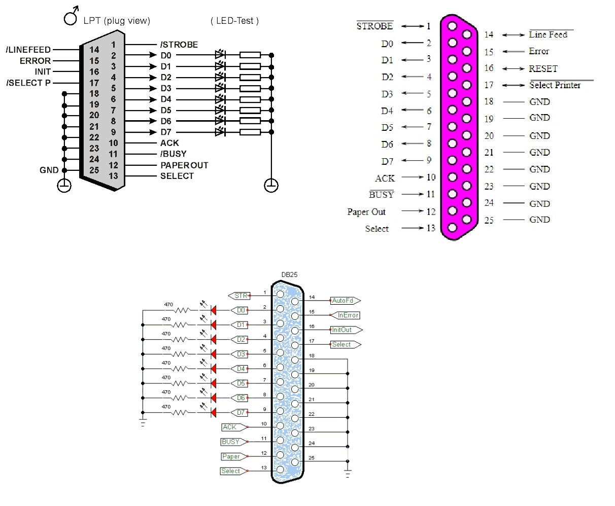
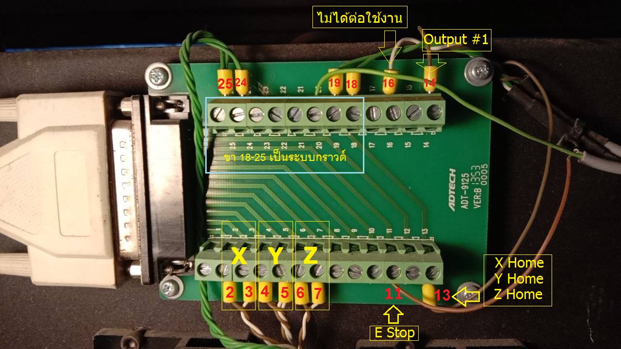
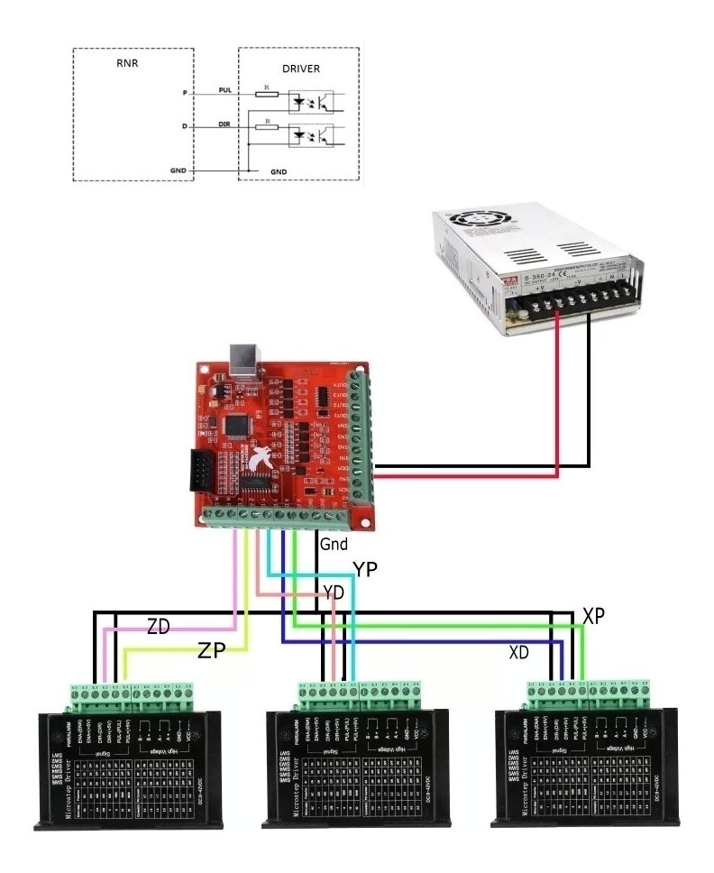
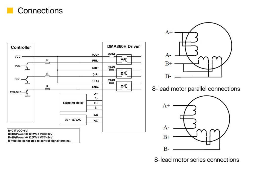
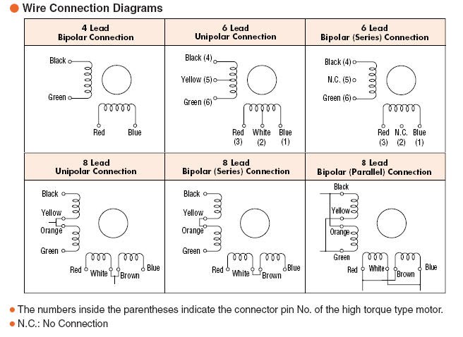
01. Wiring Diagram
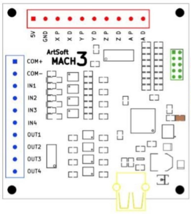
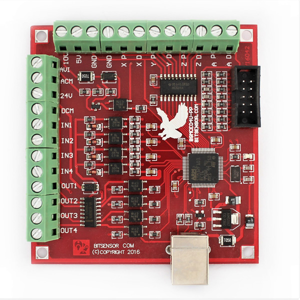
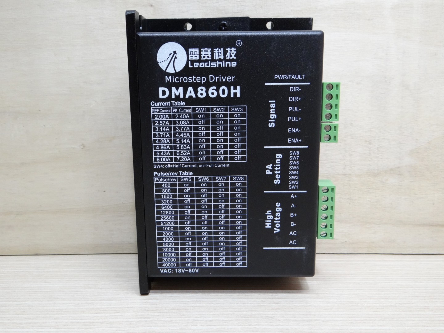
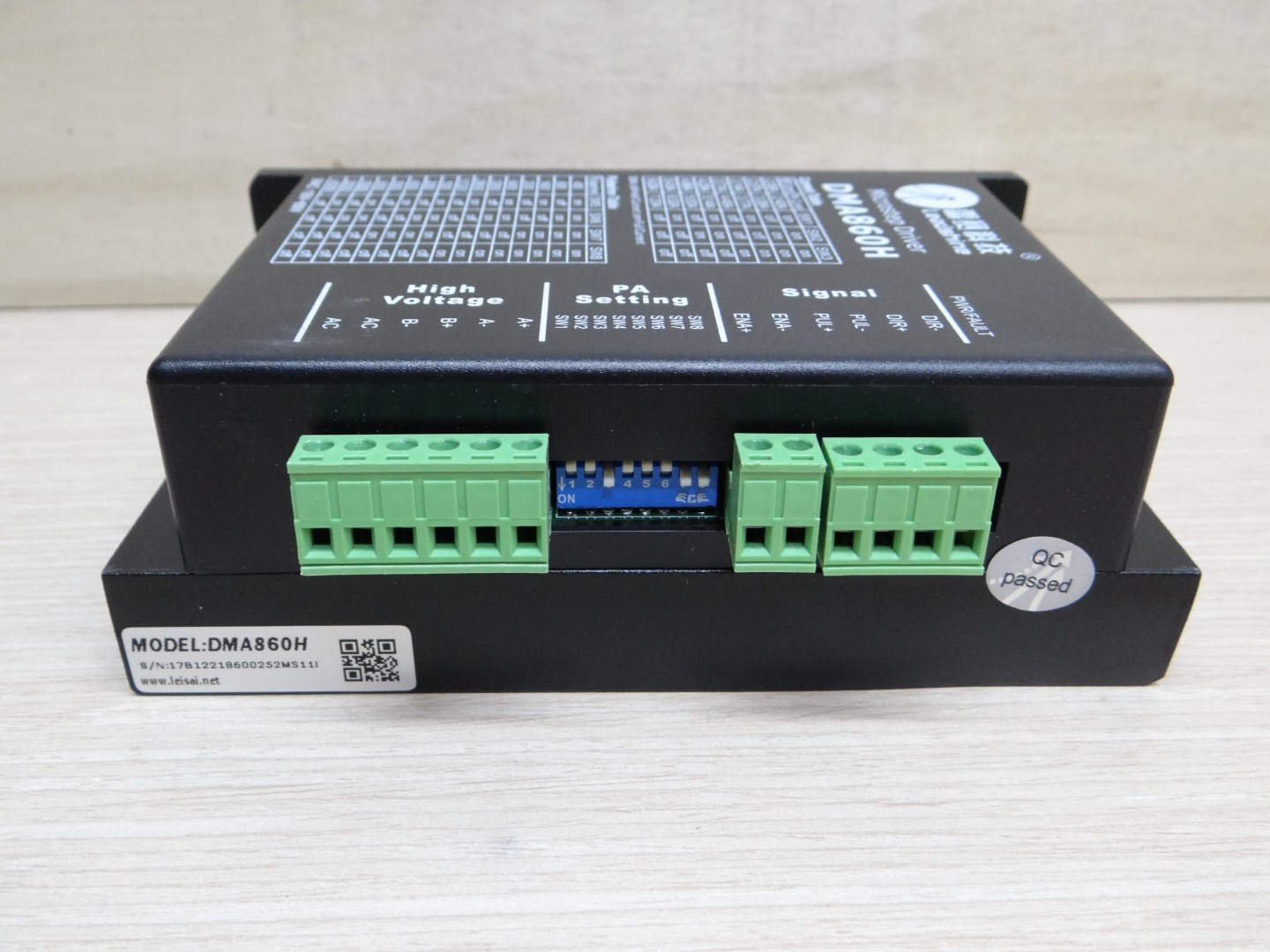
02. Diagram of the Mach3 USB Controller:
Red Terminals - Step and direction signals to connect to stepper motor drivers.
Yellow - USB Connector
Brown - Status LED
Blue - Input/Output Terminals
Green - Hand wheel connector
Controller board dimensions:Mounting dimensions are 69.85 mm in the short side and 73.66 mm in the long side.
Overall board dimensions are 77.47 mm on the short side and 81.28 mm on the long side.
First Use:For the first time the user of the RNR motion control card will need to make some necessary settings. First, install the Mach3 software and remember where the Mach3 software is installed. Copy the Plugins RnRMotion.dll file to the Mach3 Plugins folder.
Connect one end of the USB cable to the RNR universal motion control card and the other end to a computer. This product adopts the drive-free design. The Windows system can automatically detect the RNR universal motion control card and does not require the user to additionally install the device driver. If you click on the device driver installation icon on the bottom right of the desktop, you will see a pop up window dialog box that should show "RNR ECO MOTION 2.0".
For the first time, the RNR universal motion control card is connected, the system detection takes about 10 seconds. After the system correctly detects the RNR motion control card, the blue LED will light up. In this way, we know that the RNR universal motion control card can be used.
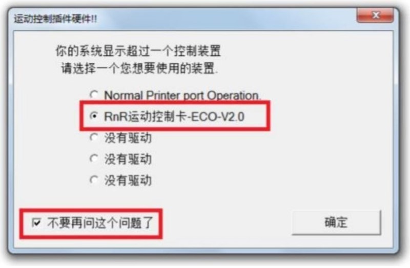
03. Next, start the Mach3 software. When Mach3 software is started, a pop-up control dialog selection screen will appear.
Select [RnR motion control card -ECO-V2.0] After the above operation, we can use Mach3 software to control our machine tools and other automatic equipment.
Pulse output:
Connection (step / servo) motor driver RNR motion control card can control 4 motors, respectively named X
axis, Y axis, Z axis, and A axis. Each axis motor control signal has a 2: command pulse signal
P four-axis (a signal corresponding to the "XP", "YP", "ZP" and "AP" and the direction signal D a four-axis (signal corresponds to the "XD ", "YD", "ZD" and "AD"). The motor driver signal Interface usually has a single-ended or differential mode.

04. Differential Mode:
For the of the motor to drive in a differential manner, wire the RNR motion control card as
shown in the image.
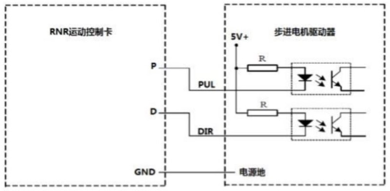
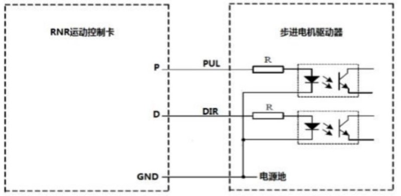
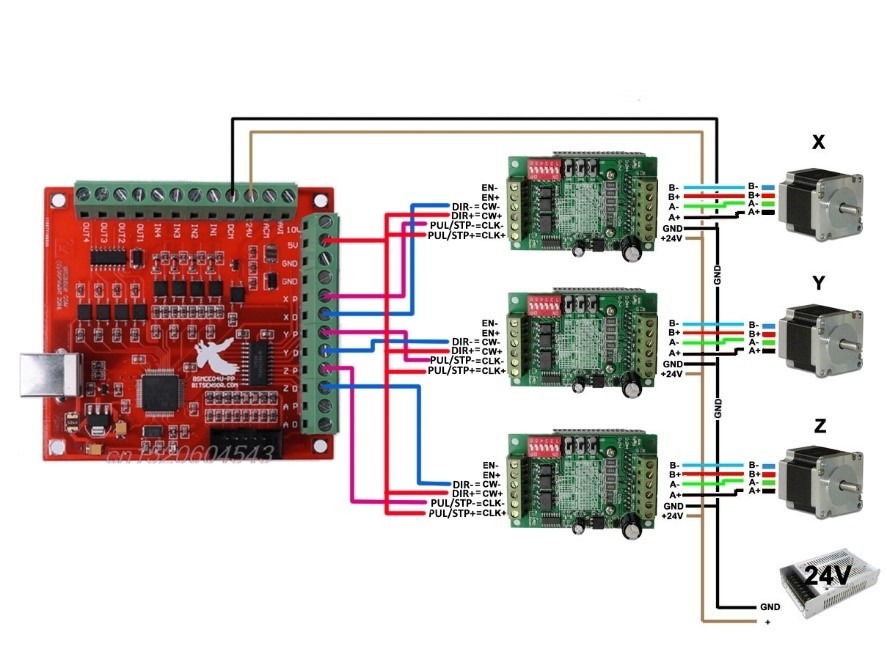
05. Single-Ended:
Interface to the single-ended motor driver usually has two forms. The most common type is that one end of its internal signal isolation optocoupler is connected to the internal 5V power supply. This kind of driver input interface is the same as the RNR motion controller card wiring in this image.
Addition Information on the driver signals and the 5v terminal:
RNR motion control card pulse output ports includes a pair of power output 5V terminals (5V, GND), this provides for 5V DC power supply terminals for the motor driver input interface for wiring. No special requirements, please avoid introducing other power lines on this interface. When an axis direction of movement with the expected direction of motion during reverse operation, the motor output can be altered [(Motor Outputs)] in direction) interface [Mach3Dir Low Active Item to reverse the direction of motion. When a shaft of the motor running, sounds very harsh, the output pulse polarity is not required with the motor driver phase reversed. you can try [(Motor Outputs)] Mach3 changes in configuration interface the [Pulse Low Active (active low pulse)] option to change the output illustrating Pulse polarity.
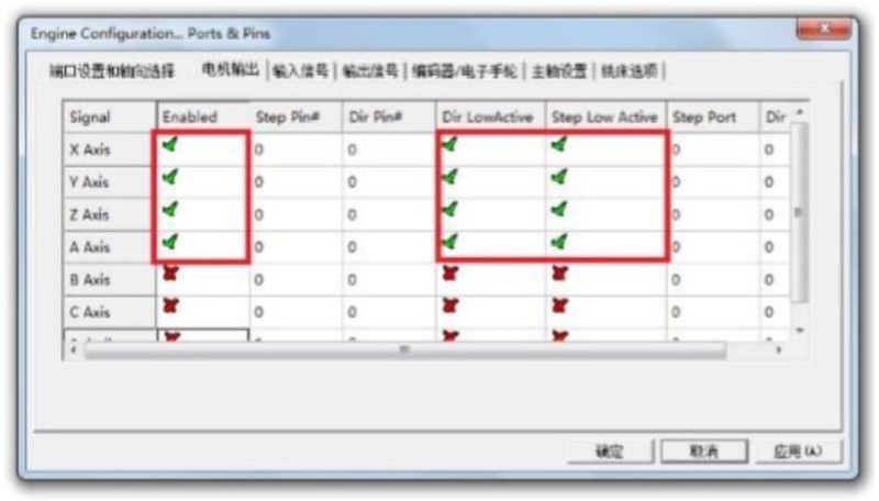
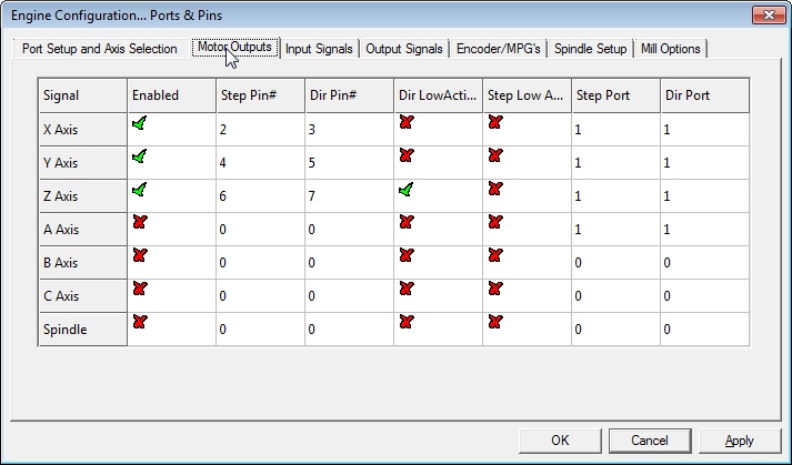
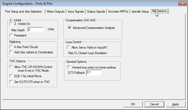
06. Note that the RNR motion control card output signal is "1" (high level) at this time , the motor driver optocoupler output signal is "0"; RNR motion control card the output signal is "0" (low when level),the motor driver optocoupler output signal is "1." Therefore, the Mach3 must be Motor Outputs in configured as Low Active. Configuration methods: Select Menu [Set (Config)], select [port / pin pin (Ports and Pins)], select Motor output (Motor Output)] p, modified as in the image.
07. Another form of motor controller in single-ended mode, signal isolation optocoupler with one end of the internal connected to the internal power ground. This kind of driver input interface is the same RNR as the wiring diagram of the motion control card in this image.
08. Slave Axis Setting:
Some mechanical devices adopt the gantry structure which may need a dual motor drive. RNR motion control card may be provided as a slave axis, it can be
specified with the A axis stepper motor to move the gantry. along with the X axis stepper motor.
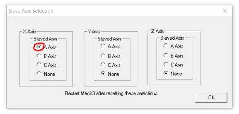
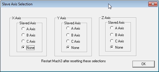
To set the A axis as a slave axis:
Select the Mach3 menu [(Config)], select [(Slave Axis)], You will see a dialog box as shown in the image
The A axis becomes the slave axis of the X axis. When the X axis moves, the A axis will X move synchronously. When the X-axis performs a home operation, the A-axis is automatically balanced (see the Automatic Homing section).
09. Input Signals:
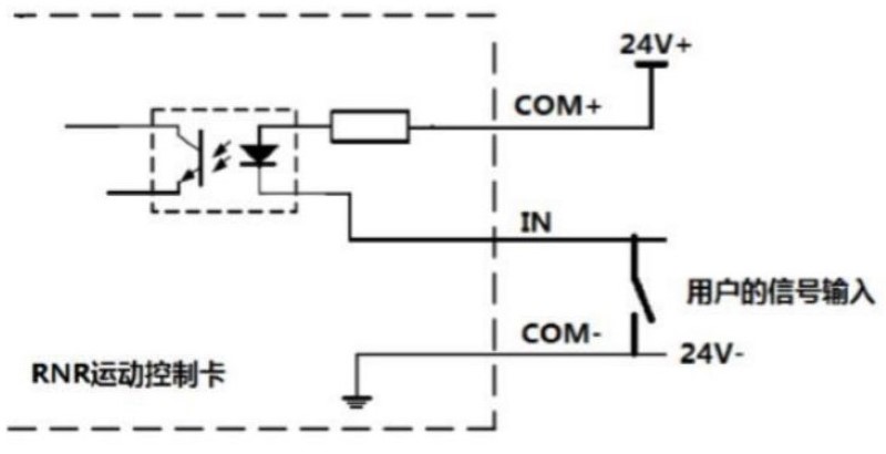
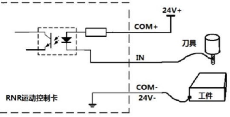
RNR universal motion control card provides four optocoupler isolated signal inputs. As needed,a user can flexibly be defined as input signals the signal on the knife, homing signal, stop signal, the limit switch signal input or user-defined input signal. The signal input circuit of the RNR all-round motion control card is shown as in the image.
The user should connect the COM+ terminal to an externally supplied positive 24V of the 24V DC power supply should be DC power supply; the negative terminal connected to the COM- terminal. When the IN1..IN4 terminal is negative terminal of the 24V power supply shorted to the, the loop is closed and the corresponding input signal is logic "1"; the IN1..IN4 terminal is open and the corresponding input signal is logic "0".
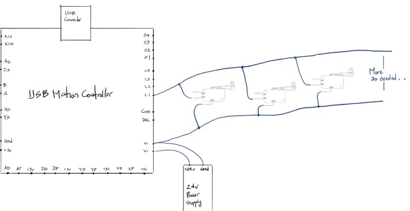
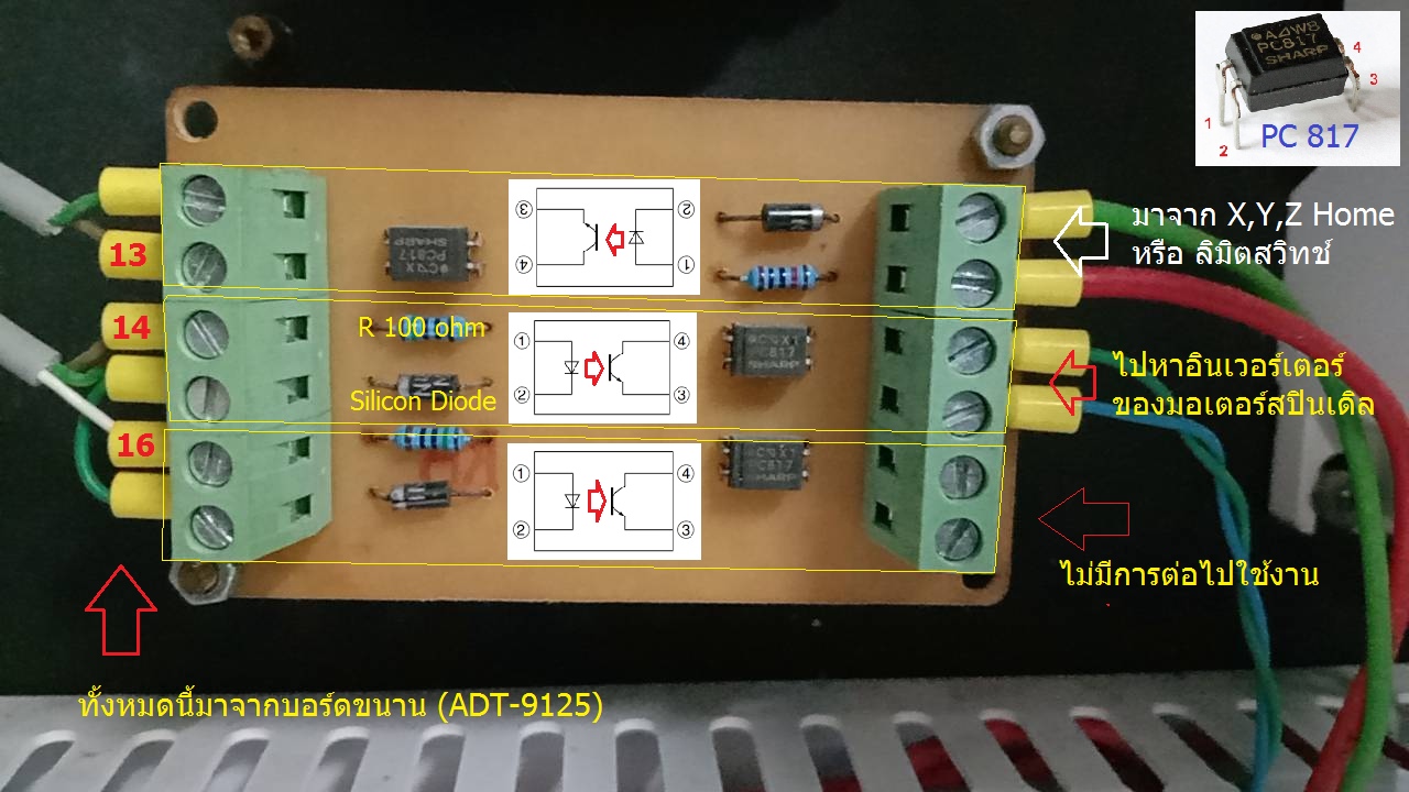
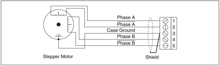
10. This is a simple sketch of how the limit switches should be connected to the Mach3 USB board. You will need an additional power supply to power this portion of the board. 24V is not necessary. A 12 volt source coming from a PC power supply or AC adapter should suffice.
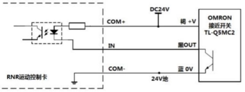
11. Wiring for the input signal
The signal input terminal is often connected to the proximity switch, mechanical limit switch or a photoelectric switch. The image shows the wiring for a proximity switch OMRON proximity switch TL-Q5MC2 (TL-Q5MC2 DC 3-wire, the NPN type, the power supply voltage DC12-24V,collector open output)
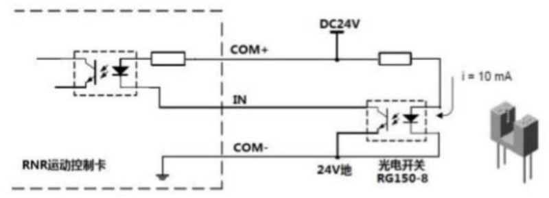
12. Photoelectric switches are often used as limit switches or origin/home switches by photoelectric RG150-8(light emitting diode photoelectric switch RG150-8 maximum current 50mA, NPN type open collector output.), For example, RNR versatile motion control card photoelectric switch wiring: in the image
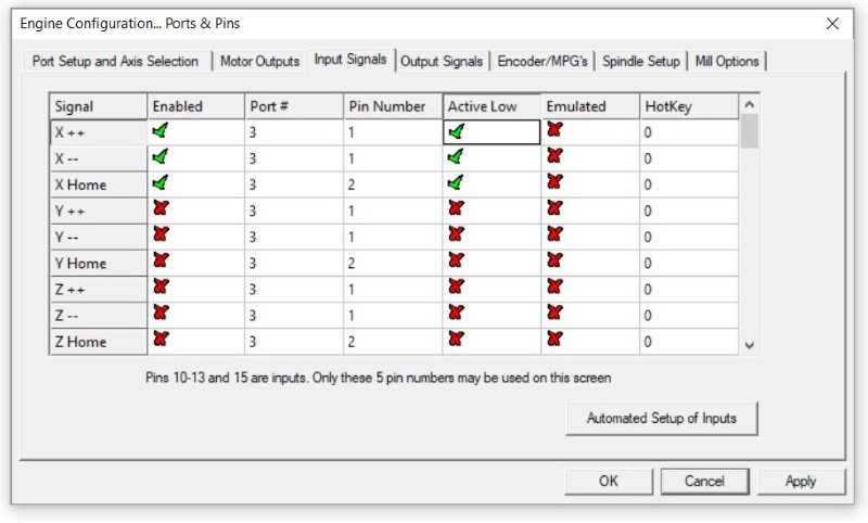
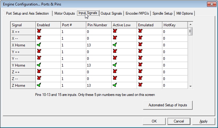
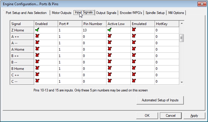
13. Photoelectric switches are normally open and when the optical gap is blocked, the photoelectric switch is turned off. Therefore, the signal input terminal is always logic "1" and becomes logic "0" when blocked. This is contrary to typical limit switch operation. For this configuration, we must configure the corresponding input terminal to [Active Low via Mach3 software]. The configuration method is: select the menu [Config], select [Ports and Pins], and then select [Input Signals] Page, as shown in the image.
It is assumed that the user will connect the photoelectric switch to the IN1 terminal as the X-axis limit switch. At this point, you should check the Active Low of X++ and X-.

14. Emergency Stop Button
When the user presses the [Emergency Stop] button during processing, the machining process will be terminated immediately. This eliminates accidents the first time they occur. For safety reasons, we strongly recommend that you add an external input (IN1..IN4) terminal to the emergency stop button. The Emergency stop button wiring diagram as shown in the image.
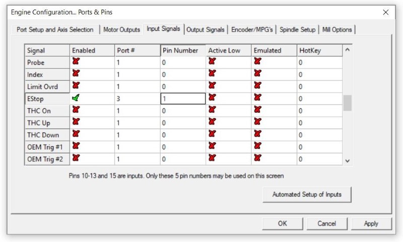
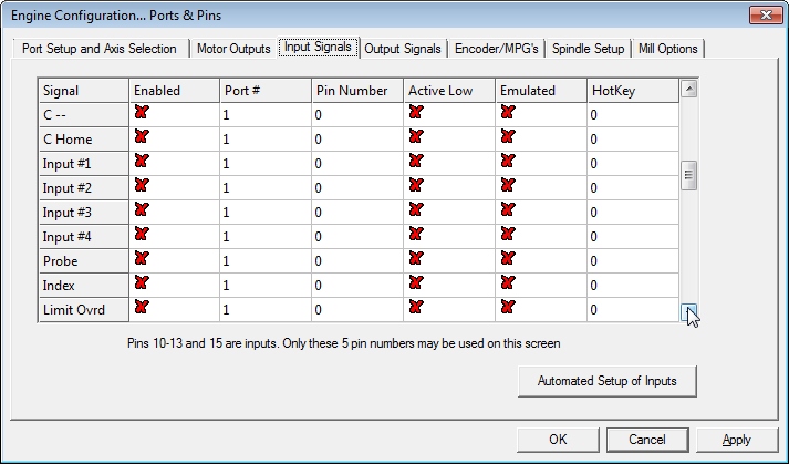
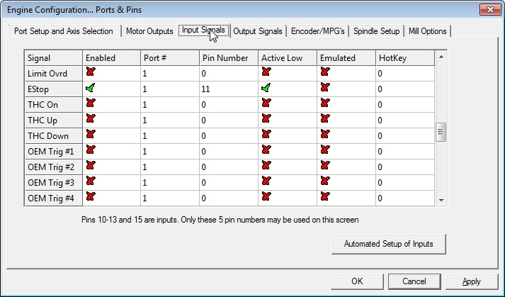
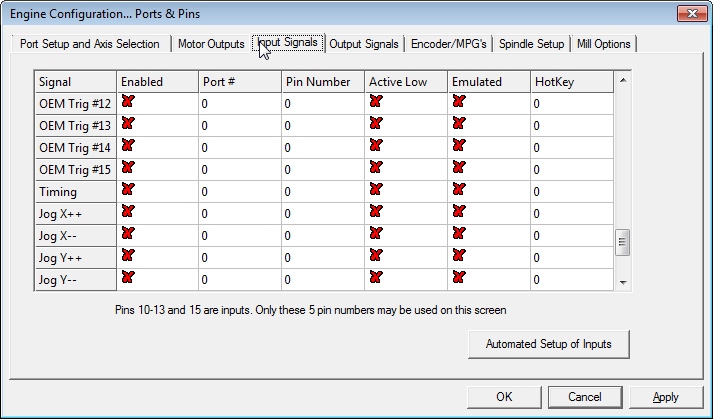
15. Assume that the user connects the emergency stop button to the IN1 terminal. Accordingly, we need in to make configuration Mach3 software. The configuration method is: Select [Config], select [Ports and Pins], and select [Input Signals] page. Pull down the scroll bar, find the line with the name [Signal] [EStop],line of the Estop line check the [Enable], and set the Port # to 3. Port 3 is set means that the signal is processed by the RNR motion control card. Other port numbers indicate that this signal is not related to the RNR motion control card. Setting the Pin Number to "1" means that this signal is connected to the IN1 of the RNR Motion Control Card terminal. After the configuration is
complete, click OK.
Try running some G-Code and press the emergency stop button on the terminal IN1. Observe that the machine will stop.
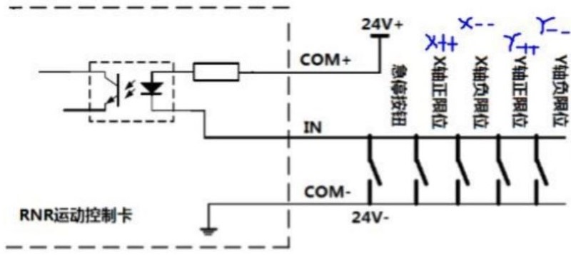
16. Limit
When the limit switch is activated, the machining process will terminate immediately. This can effectively prevent the tool from moving outside the work area and cause danger. This is the same effect as pressing the emergency stop button. Therefore, we recommend that users connect limit switches. In order to only use a single input terminal, all of the switches can be wired in NO (Normally Open) configuration to the same signal input terminal. Limit switches are wired as shown in the image.
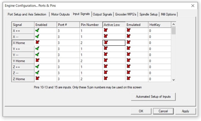
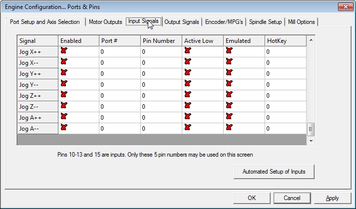
17. The assumption here is that the limit switch connected to the terminals IN1, then the configuration is as follows: Click Config, select (Ports and Pins), and then select (Input Signals). Pull down the scroll bar and find the [Signal] name [X++ (X axis positive limit)], [X--(X axis negative limit position)], [Y++ (Y axis positive limit position)], [Y--( Y-axis negative limit)], [Z ++ (Z-axis positive limit)] and other lines, the Enable [check]the {port # (port) is set to 3], the [Pin number (pin number)] is provided Is "1". As shown in the image.
Note that if the selected limit switch is a photoelectric switch, since the photoelectric switch is normally open, reference should also be a content of "input terminal wiring", the corresponding [active low (active low)]checked. In addition, when wiring, the switches are not connected in parallel, but instead should be
connected in series
18. The Automatic Return to the Origin or Homing
RNR motion control card supports the automatic return to origin function of each axis. The automatic return to each axis origin consists of four consecutive stages.
First stage is based on the set direction, with G0 (axis's rapid traverse) rate the percentage as given by the [Speed%] parameter in Mach3 towards the origin until it touches the origin switch;
Second stage: G0 rate from the origin switch, is set to fall back from the stop;
Third stage: the rate of movement at a rate of 1/10 of the first stage, gradually toward the moving origin,the origin until the touch switch stops with touches the origin switch at a very slow rate to ensure the accuracy of the origin;
Fourth Stage: In the same stage as the second stage, it will stop at the G0 rate after going back to the set distance. This ensures that the axis completely leaves the origin switch.
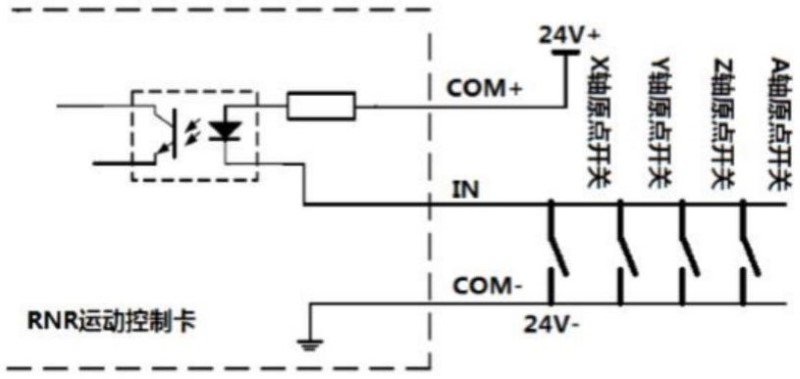
As described in the "limit switch setting" in the previous section, in order to use only one input terminal, the origin switches of the four axes can be connected in parallel and share one input signal terminal (IN1..IN4).
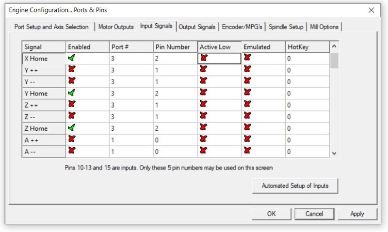
19. Mach3 software must be configured accordingly for the parallel normally open wiring configuration. It is assumed that the origin or home switch is connected to the IN2 terminal. The configuration method is: at the menu [Config], select [Ports and Pins], and then select the [Input Signals] page. Pull down the scroll bar to find the [Signal] names [X Home (X-axis home switch)], [Y Home (Y-axis home switch)], [Z Home (Z-axis home switch)], [A Home (A-axis origin) Switch)], select [Enable] to select [Port #] as "3" and [Pin Number] as "2". As shown in the figure:
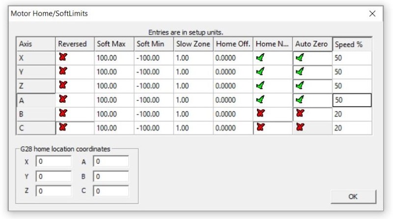
20. Homing rate configuration method
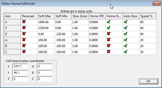
Select the menu (Config), select (Homing / Limits) in [motor homing / Soft Limits)] (Motor Home / interface, find the line where the axis is located. Modify by changing[Speed %] the value. For example, we expect to perform with 50% of the G0 (Axis Rapid Move) rate homing, then set [Speed %] to "50". When returning to the origin, the direction of the axis movement is related to the position of the origin switch. If the origin switch is mounted on one end of the negative axis of the shaft, the [Home Neg] item should be checked. If the origin point switch is installed on one end of the positive axis of the shaft, [Home Neg] should be crossed as shown in the image
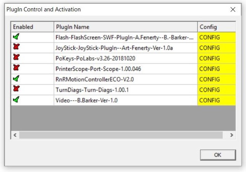
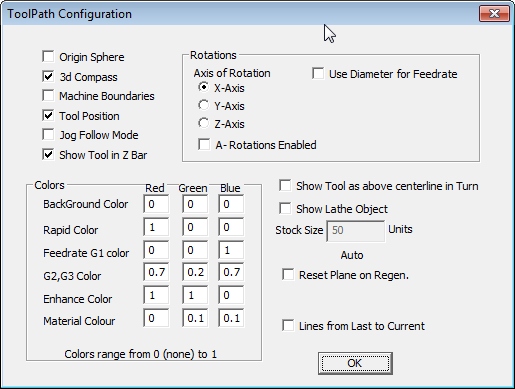
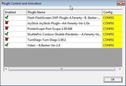
21. The second and fourth phases of the automatic return to origin process are the back-off phase after returning to the origin. Set distance fallback method is: select the menu (Config), select (Config Plugins).
In the pop-up window, find the [RnR Motion Control Card-ECO-V2.0] line and click [CONFIG] to display the [RNR Universal Motion Control Card Parameter Settings] dialog box.
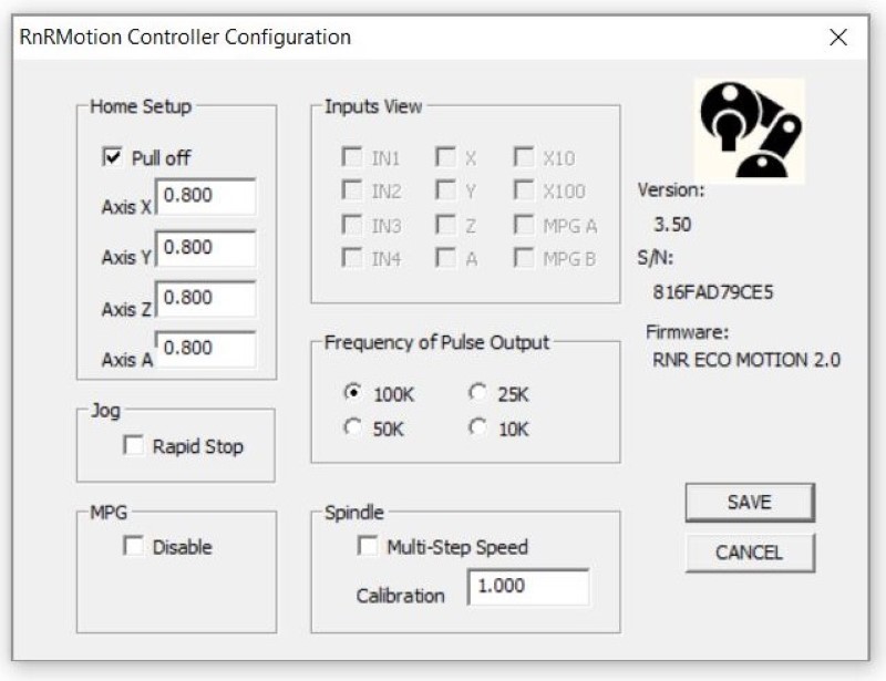
22. In the Return to Zero setting box, change the back-off distance for each axis. As shown in the image, change the axes to "0.8". In this way, the return distance is "0.8" units when you return to the origin. Also, click the pull off checkbox to enable the pull off. Setup is completed, do not forget to click [Save].
The Automatic Origin Homing of Axis with Slave Axis
The axis and its corresponding axis of the slave axis must be equipped with a home switch, and the origin slave axis and the origin switch of the switch of its corresponding axis should be connected from the two signal input terminals. Here assumed is that the slave axis A-axis is the X axis, the X axis is mounted a home switch, A shaft is home switch mounted. When the X-axis performs a home operation, in the first stage, both the X-axis and the A-axis move toward the origin. The axis that first hits the origin switch will stop moving, and the other axis will continue to move until it touches the origin switch. The third stage is similar to the first stage. In this way, the two axes are balanced when they are automatically returned to the origin.
23. The automatic tool setting
RNR motion control card supports the automatic tool setting function. In Mach3, automatic tool setting can be used to automatically measure and compensate the tool length, position the workpiece, find the center of the workpiece, and find the center point of the workpiece. To use the automatic tool setting, an RNR universal motion controller card needs a signal input terminal (IN1..IN4) to be attached to the tool setter. This setter is also called a Z-Axis touch plate. The nature of the tool holder is a micro switch. Therefore, the self-made touch plate is very simple. Two wires, a connecting tool or edge finder, a connection to a single-sided printed circuit board or a connected workpiece. When the tool or edge finder hits circuit board the copper layer or metal workpiece, the line is turned on and the tool setting signal input is completed.
Select an input signal at an input signal terminal IN1..IN4 signal as a touch plate.
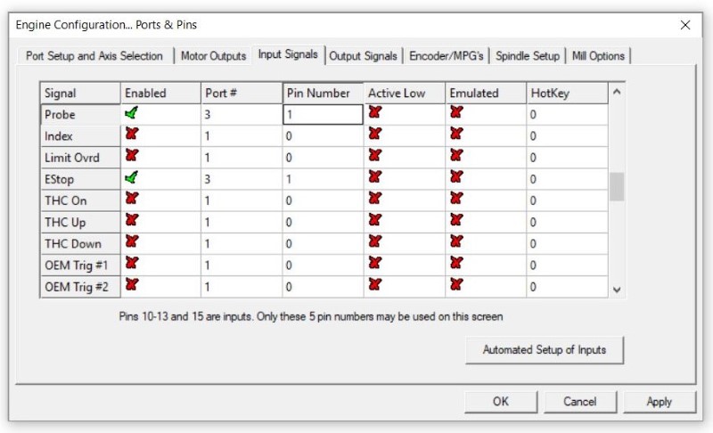
24. Assuming the input signal is selected as a terminal IN1 signal input tool. The setting method in Mach3 is: select [Config], select [Ports and Pins], and then select [Input Signals] page. Find the line where [Signal] is [Probe], check the [Enable] item, modify [Port #] to "3", and modify [Pin Number] to "1".
In Mach3, the specific tool setting process is accomplished through VBScript script code. VBScript script code requires the user to write according to the actual situation. Many VB scripts can be found on the internet. You will need to customize the code for your application.
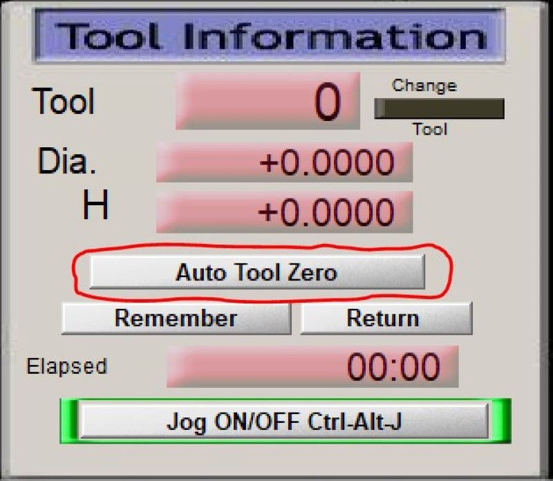
25. Automatic Tool Clearing
Automatic tool clearing function helps the user to remove the tool length and workpiece thickness, and the Z defines the zero coordinate of axis to the machining surface of the workpiece. Mach3 does not provide automatic zeroing for the script code. We need to program the automatic tool zeroing function. Programming steps: Select menu (Operator) and select (Edit Button Script), and then find the (Program Run) screen, click (Auto Tool Zero) button.
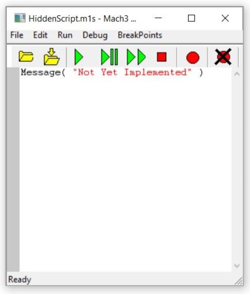
26. As shown in the figure, Mach3 will pop up the scripting window, as shown in the
image.
Delete the original script code in the window and replace it with code that will work for your application.
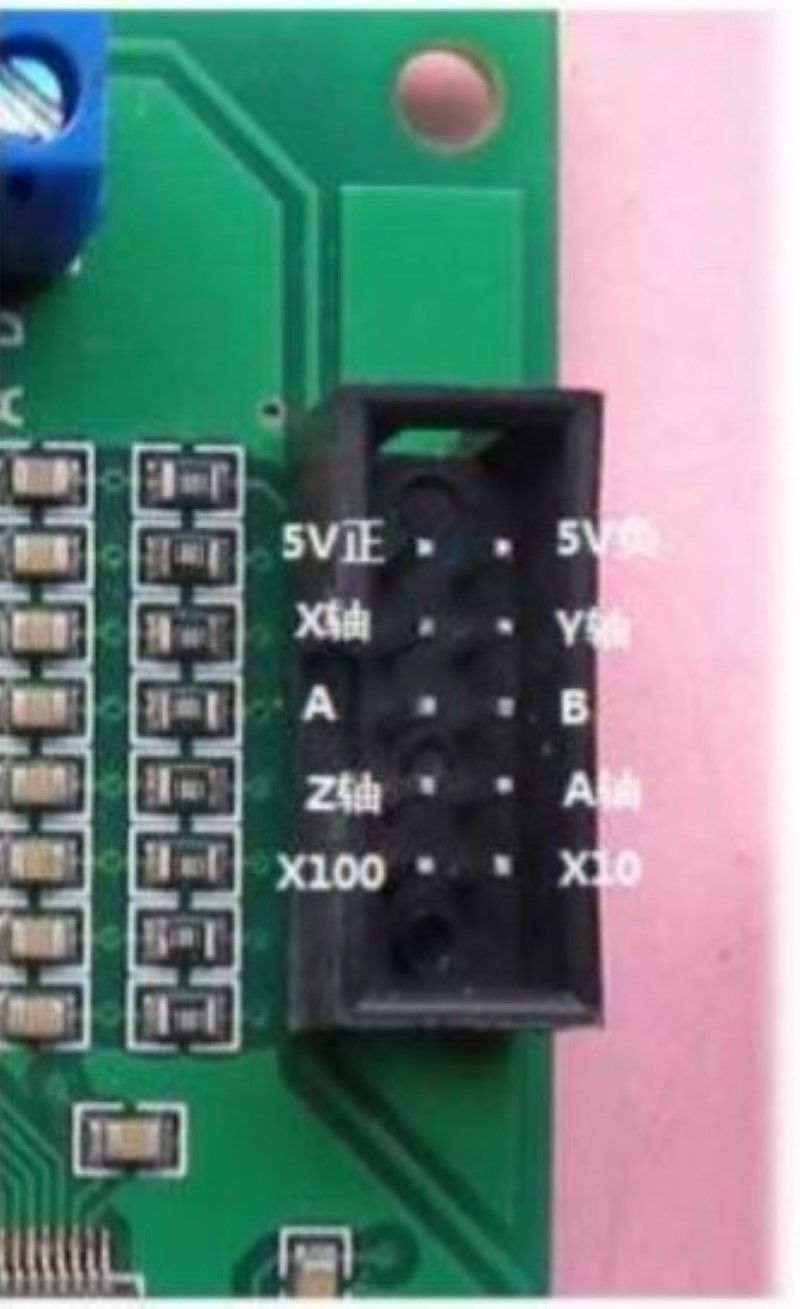
27. The Handwheel Interface
RNR motion control card provides a handwheel interface to the user-supplied handwheel. Note that the handwheel interface has a withstand voltage of 5V, so only connect DC 5V powered handwheels. When the handwheel interface input exceeds 5V, it will cause damage to RNR's motion control card.
Below Each pin is described as follows:
- 5V positive and 5V negative: DC 5V power supply is available, which can be used to supply power to the handwheel
- X-axis, Y-axis, Z-axis, A-axis : a shaft connected to the hand wheel switch, used to select the desired axis jog
- A and B: connecting the hand wheel encoder outputs A and B
- X10: handwheel rate 10 times magnification
- X100: handwheel The rate100x
Enhancement handwheel interface is compatible with Weihong system handwheels.
WeiHong handwheel 15 Plug pin numbers. Weihong Handwheel Pin Definitions Connect to Handwheel Interface
1 VCC,L+ 5V Positive
2 A - A
3 B - B
4 Empty
5 Empty
6 X1
7 X10 - X10
8 X100 - X100
9 4 Axis - A Axis
10 Empty
11 COM Terminal, 0V,L - 5V Negative
12 Empty
13 Z Axis - Z Axis
14 Y Axis - Y Axis
15 X Axis - X Axis
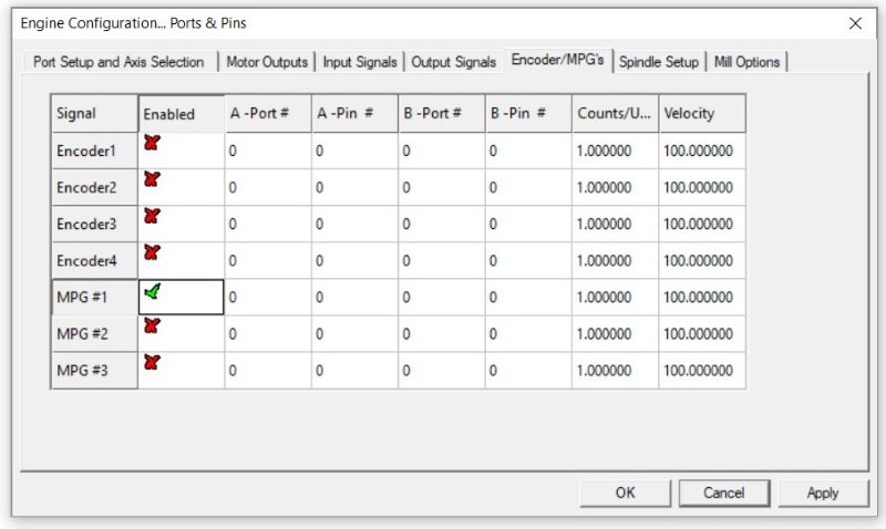
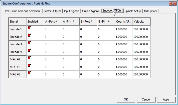
28. Mach3 Handwheel Setting
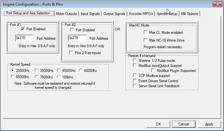
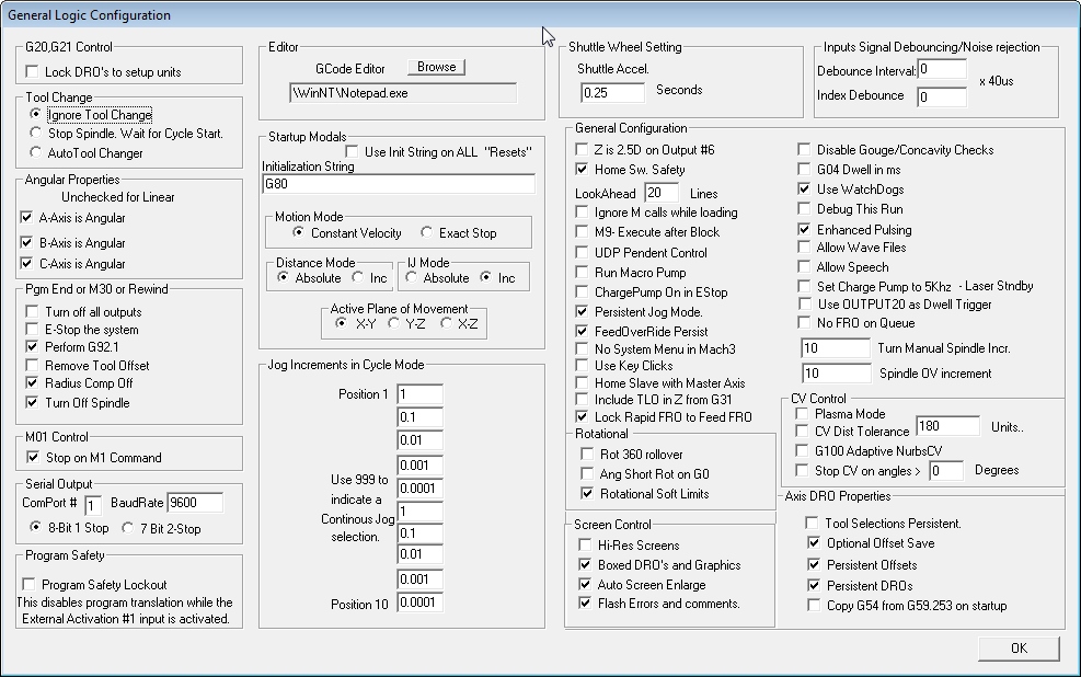
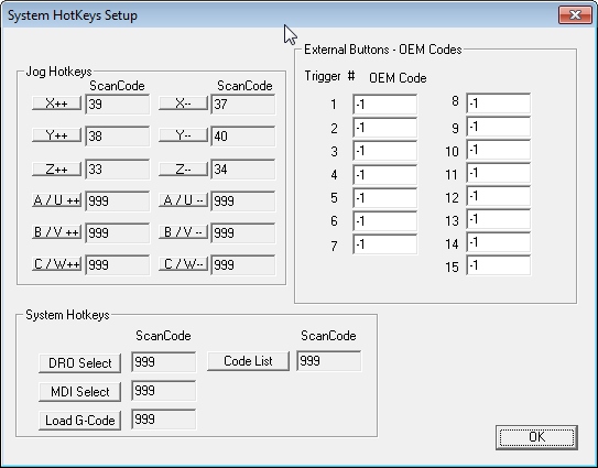
Connecting the handwheel, the Mach3 must be set to enable handwheel jogging. Setup method: Select Menu [Set (Config)], select (Ports and Pins), select (Encoder / MPG "s) page, the [MPG # 1} [Enable] is checked, as shown in the image.
Press [OK] to save the setting

29. Press [Tab] on the keyboard to call out the Mach3 Handwheel control.
Click the [Jog Mode] button to switch the jog mode to [MPG (Handwheel)] mode and tap [Alt A] to switch the X axis selection as shown above. Gently rotate the handwheel encoder to see if it can control X-axis movement.

30. Handwheel Interface as an Extended Input Signal
If you do not need to connect a handwheel, you can use the handwheel interface as extra input signals. The handwheel conector will provide 8 more input signals, and with the previous 4 signal inputs IN1..IN4, will provide a total of 12 input signals.
The signal input hand wheel interface correspond to the terminals of the following:
- X axis: IN5
- Y axis: IN6
- Z Axis: IN7
- A axis: IN8
- X10: IN9
- X100:IN10
- A:IN11
- B:IN12
Note: IN5..IN12 handwheel input terminal does not support the interface corresponding to the limit or homing position, tool setting, only as a regular input of the switch used (typically used as a connection control panel). wiring signal input to the X-axis, for example, we need the X-axis access to Input signal internal Interface schematic principle handwheel As follows:
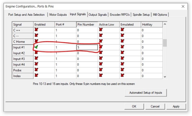
31. When the signal input switch is closed and shorted to ground, the logic signal "1" is input to the X axis. We select the Mach3 menu [Config] and select [Ports and Pins] and then select the [Input Signals] page. Drag the scroll bar to find the line where [Signal] is [Input #1],[Enable] select, and change [Port #] to For "3", change the [Pin Number] to "5" so that the Mach3 input signal [Input #1] corresponds to the input of the handwheel X. Select the
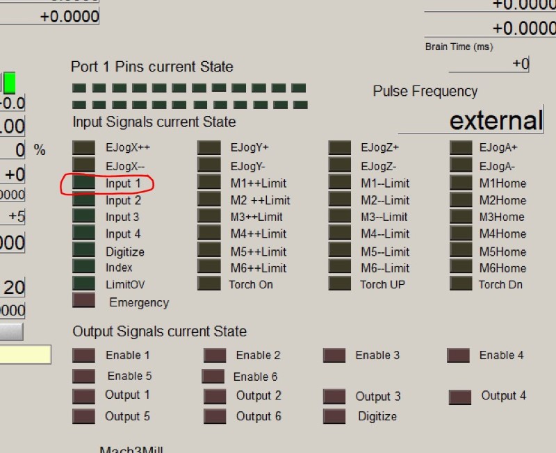
32. Look at the Diagnostics page of Mach 3. When you close the X axis external switch, you will see Input 1] Display turns green.
33. Output Signals
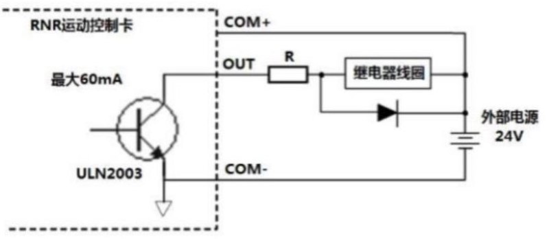
RNR motion control card provides four optocoupler isolated outputs. An output terminal adopt Darlington ULN2003, capable of driving an external relay or indicator. Drive capacity is 60mA. Wiring of output signal to relay.
COM+ and COM- of the signal output terminal block respectively connect the positive and 24V DC power supply negative poles of the. The output terminals OUT1..OUT4 are connected to the relay coil via a current limiting resistor (relay the other end of the coil is connected to the positive terminal of the 24V power supply). Wherein the resistance of the current limiting resistor based on requested relay.
Spindle Motor Control
Mach3 supports spindle motor control. Mach3 offers three spindle motor control methods.
The first is relay mode. Mach3 outputs control signals through two signal output terminals.
The second is the PWM mode. In this mode, Mach3 through the signal output outputs the PWM signal with a certain duty cycle output terminal that will create a (DC) spindle motor speed control.
The third method is the pulse method, which is mainly used to control the servo motor. The RNR motion control card does not support this mode.

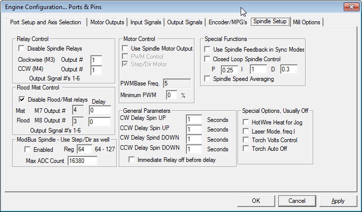
34. Spindle Control in Relay Mode
The relay mode, the spindle motor drive signal output terminal using two relay switches on or off to achieve reversing the spindle motor. Suppose we need the signal output terminal OUT1 to drive the motor forward rotation relay and the signal output terminal OUT2 to drive the motor reversal relay. In Mach3, select the menu [Config], select [Ports and Pins], and select the [Spindle Setup] in the popup dialog page. In (Relay Control) box, ensure that (disabled Spindle relays) is not checked; in [clockwise output # (Clockwise Output)] Fill "1"; counterclockwise in [ Output # (CCW Output) and fill in "2".
Press [OK] button to save the settings. The user can connect the indicator OUT1 and OUT2 (refer to the previous section) for debugging. When the program "M3" is executed, OUT1 output signal will be seen; when the program "M4" is executed, the OUT2 output signal will be seen; when the program "M5" is executed, the OUT1 and OUT2 are turned off. Use the MDI page to enter the M3, M4 and M5 codes.
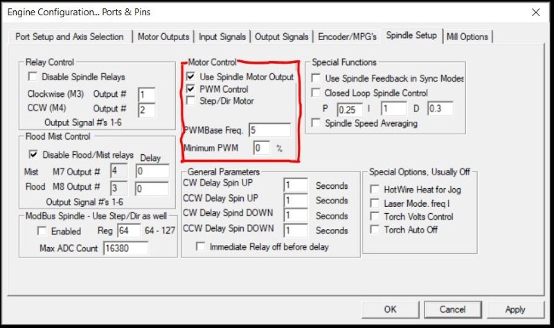
35. PWM Mode
Suppose we need to output PWM (pulse width modulation) signal on terminal OUT3 to drive the spindle motor power supply relay, motor speed adjustment is achieved. In Mach3: Select [Config], select [Ports and Pins], and select [Spindle Setup] page in the popup dialog box. In the Motor Control box, check Use Spindle Motor Output and select PWM Control.
[Use spindle motor output] is checked, Mach3 will automatically enable the spindle motor output pin. Click OK when the pop-up happens that will say "Spindle Motor has now been enabled. Ensure you set its pinouts.
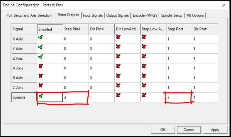
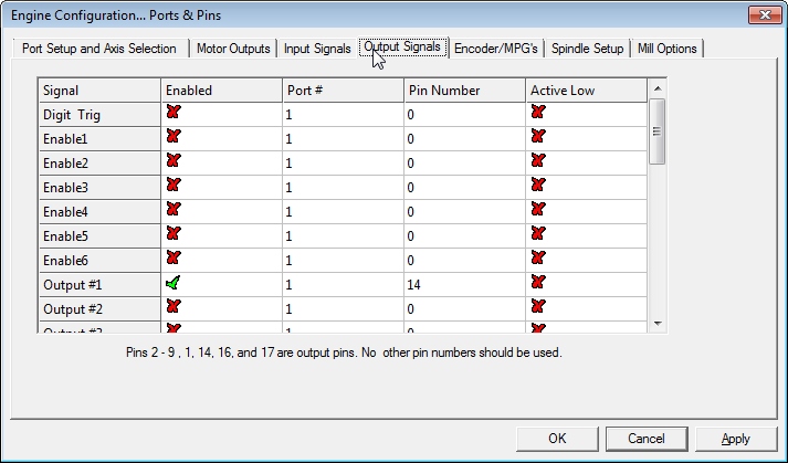
36. Next, select the Motor Outputs tab. At the line where [Signal] is [Spindle], check [Enable], modify [Step Port] to "3", modify [Step Pin#] to "3", and specify OUT3 as Is the output terminal of the PWM.
Press [OK] button to save. Connect the indicator (refer to the previous section) to OUT3 for debugging. When the program "M3"executed is, OUT3 output signal can be seen

37. In Mach3's [Program Run] page, click on the green [Spindle Speed] bar in [and change the value of [SRO%] to be less than [100%].
In this case, it can be observed OUT3 external indicator starts blinking in the diagnostics page (PWM output signal).
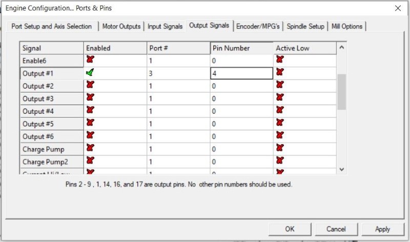
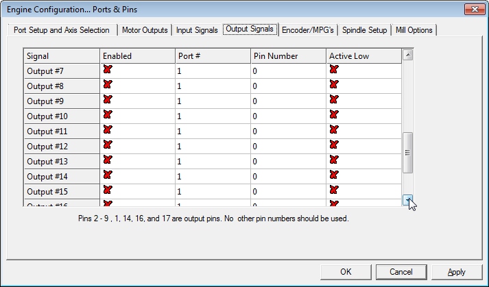
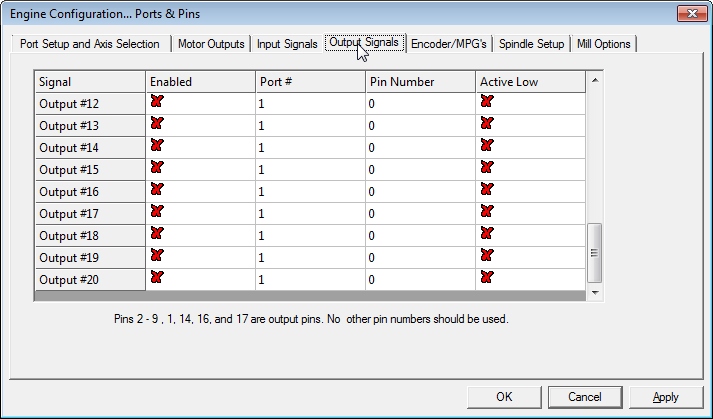
38. The Output of Other Signals
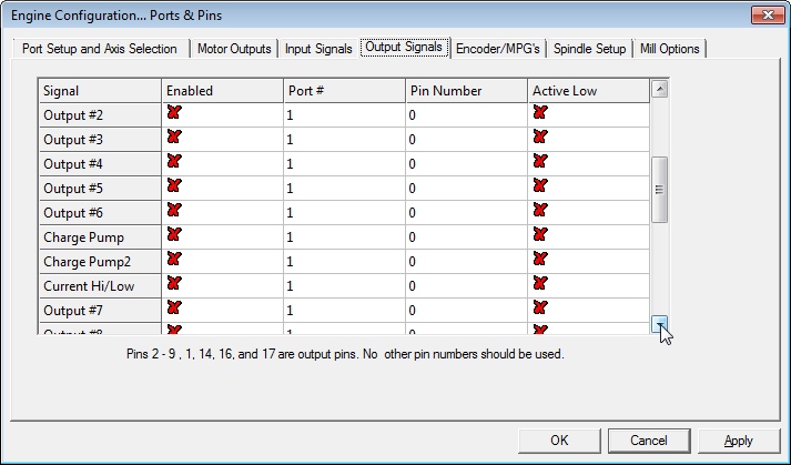
The signal terminal can be assigned to output pins OUT1..OUT4 in Mach3 from the script and can be manipulated in Mach3. For example, we need to assign OUT4 to Mach3's [OUTPUT#1]. Setting method: Select [Config], select [Ports and Pins], and select [in the popup dialog box Output Signals] page. Find the line where [Signal] is [Output #1], check [Enable], modify [Port #] to "3", and modify [Pin Number] to "4". When the changes are made, click OK to save.


 :
:  กระทู้เมื่อเร็วๆ นี้


 )
)


